
VSEditは回路図とVerilogを融合する設計ツールです
VSEdit is a design tool that fuses schematics and Verilog
VSEditは回路図入力の常識を破ってしまいました
従来の回路図入力では当たり前だったワイヤーパスの編集機能がVSEditにはありません。接続したいピン間をドラッグすることで接続され、ワイヤーは全て出力ピンから入力ピンへ曲線で示されます。この無謀とも思われる入力法と表示法を採用したことで、回路図入力の最大のストレスである「配線を綺麗に整理する」という義務感からあなたを開放します。あなたはただ「論理に必要な接続」を思考するだけです。配置の変更も全くスムースです。ただし、見た目には美しくないかも知れません。それについては改良の余地があり、改良版を企画中です。
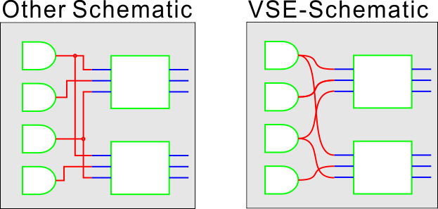
VSEdit has broken the common sense of schematic entry: VSEdit does not have the wire path editing function that is commonplace in conventional schematic entry tools. All wires are shown as curves from output pins to input pins. By adopting this seemingly reckless input method and display method, you are freed from the biggest stress of drawing schematics, the sense of obligation to “arrange the wiring neatly”. With VSE, you just think “logical connections”. However, looks may not be beautiful. There is room for improvement about it, and an improved version is being planned.
回路図なんて面倒、記述言語の方がいいでしょ! 本当に?
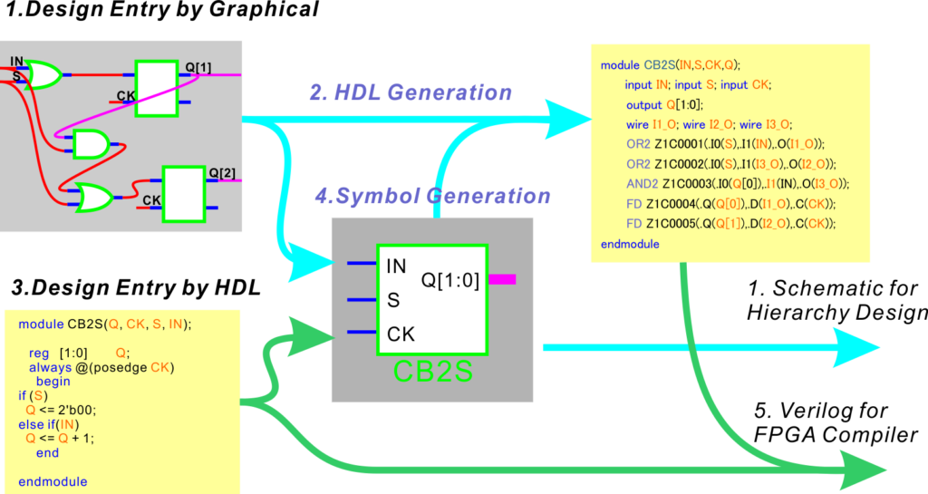
論理の記述と言う意味ではVerilogの方が楽な場合も多いでしょう。でも、Verilogで記述した20本も30本もI/Oのあるモジュールをインスタンスして接続を記述しているとき、私はイライラしてしまいます。Verilogで論理を記述して、回路図で接続できるなら、それが一番楽だと思いませんか? VSEditでは、モジュールをVerilogから書き始めることが可能です。シンボル化されたモジュールの内部が回路図オリジンなのかVerilogなのかは上位層の設計では区別がありません。

Schematics are a hassle, description languages are much better! ”Is that really true?” In terms of logic description, Verilog is probably easier in many cases. However, I get frustrated when I’m writing modules with 20 or 30 I/O lines written in Verilog and connecting them. Wouldn’t it be easier if you could write logic in Verilog and connect it in a schematic? VSEdit allows you to start writing modules from Verilog. The upper layer design doesn’t care whether the inside of the symbolized module is a schematic circuit or Verilog.
VSEditの基本機能は、、
- スケマティックエントリー シンボル化された回路要素(モジュール)を図面上に配置し、接続する機能
- Verilogネットリストの生成 回路図を解析し、モジュール間を接続したVerilog記述に変換する機能
- Verilogによる回路記述 標準的なVerilog-RTLを用いて、回路図を記述するエディター機能
- ジンボル生成、編集 スケマティックかVerilogで記述された回路図をシンボルにする機能
- Verilogファイルの結合 トップ回路図以下に含まれるモジュールを展開し、1つのVerilogファイルに結合する機能
これらの機能により、VSEditは、回路図をネットリスト記述のVerilogに変換し、RTL記述のVerilogを回路図に配置できるシンボルに変換します。シンボルを使って階層構造の回路図を描くことで大規模で複雑な論理を記述できます。最終的に完成したトップ図面をFPGAの合成ツールでコンパイル可能なVerilogファイルを出力します。もっとも賢い使い方は、要素ごとのコンパクトな論理をverilog記述し、それらの統合を回路図で行う方法だと思います。これによってグラフィカルにコンポーネントを置くことで目的の論理を完成でき、同時に、長いコードを読むストレスから解放されます。
Basic Functions of VSEdit are :
- Schematic Entry: Function to place and connect symbolized circuit elements (modules) on the drawing
- Generation of Verilog netlist: A function that analyzes circuit diagrams and converts them into Verilog descriptions that connect modules
- Circuit description in Verilog: editor function for describing circuit diagrams using standard Verilog-RTL
- Symbol generation and editing: Function to convert schematics or circuit diagrams written in Verilog into symbols
- Combining Verilog files: A function that expands the modules included under the top schematic and combines them into one Verilog file
With these features, VSEdit converts schematics to netlist description Verilog and RTL description Verilog to symbols that can be placed on the schematic. Large-scale and complex logic can be described by drawing hierarchical schematics using symbols. The final completed top drawing is output as a Verilog file that can be compiled with an FPGA synthesis tool. I think the wisest way to use it is to describe compact logic for each element in Verilog and integrate them in schematics. This allows you to complete the desired logic by graphically placing components, while at the same time relieving you of the stress of reading long lines of code.
本当に使い物になるのか?
はい、私たちの代表的なイメージングシステムにはXilinxのSpartan6が1セットに最低6個使用されています。その膨大なロジックは全て、このVSEditを使ってデザインしました。社内で基本的な機能が完成したのは2011年で、それ以来、改良を重ねていますので、機能も使い心地も他のエントリーツールに負けないと思います。なお、目立ったバグはありませんし、安定性も高く、ほとんど落ちません。自分たち用に作ったソフトですからそれなりに癖はありますが、商品化に際し一層のブラッシュアップを行いました。とは言え、試してみないと信じられない、それには私も同感です。
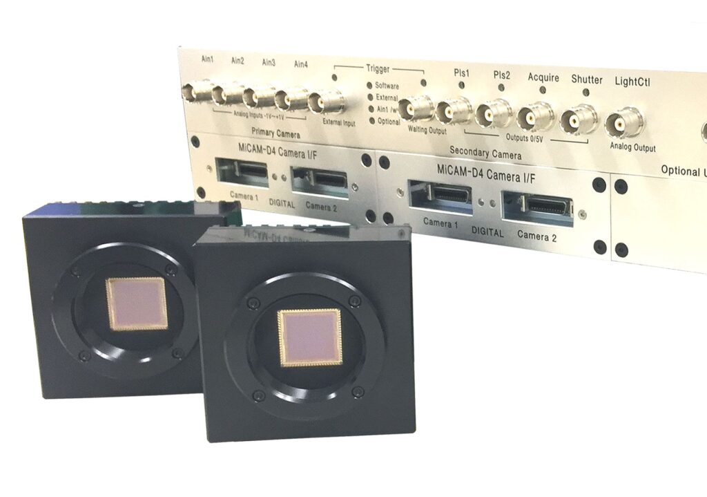
Will it really be useful? Yes, our typical imaging system uses at least 6 Xilinx Spartan6s per set. All the huge logic of the system was designed using this VSEdit. The basic functionality was completed in-house in 2011, and since then it has been improved. As a result, I think that the functionality and ease of use are comparable to other tools. In addition, there are no noticeable bugs, the stability is high, and it almost never crashes. We made this software for ourselves, so it has its own quirks, but when it came to commercialization, we brushed it up even further. That said, I agree with you that you have to try it yourself to believe it.
紹介動画をご覧ください
TODO:動画を挿入する
まずは、使ってみてください
あなたは評価版を無料ですぐに使えます。回路図に新たに配置できるモジュールの数が8個、シンボルのI/O数が8本に制限されていますが、それ以外は有料版と同等に動作します。また、ビュアーとして使う限りは、大きな回路も見ることができます。試してみて、もし、あなたの設計に使えると感じたなら、制限が緩和された正規ライセンスをご購入ください。
今だけ、、、公開記念にモジュール制限を16個、I/O制限16本に拡張した無料版ライセンスを期間限定で提供いたします。なお、このプロモーションは当社の判断で予告なく終了いたします。
- PCの推奨仕様 Required PC :Windows7 or 10 , RAM>4GB 、HDD>4GB、3GHz or faster.
- 確認済 Tested Xilinx ISE13.2-14.7 Vivado 2021.1/ Latice / Altera /
Use it immediately! You can download the evaluation version for free. The number of modules that can be newly placed in one schematic is limited to 8, and the number of symbol I/O is limited to 16, but other than that, it works the same as the licensed version. Also, as long as you use it as a viewer, you can see large circuits. If you feel you can use it for your design work, please purchase a license.
Only now, to commemorate the release, we will provide a free version license with the module number limit expanded to 16 and the I/O limit expanded to 16. This promotion will be terminated without notice at our discretion.
ライセンスの価格と購入方法
ベーシックライセンス モジュール数制限64個、I/O制限64本 30,000円(+消費税)
プレミアムライセンス モジュール数制限なし、I/O制限なし 60,000円(+消費税)
ご購入をご希望のお客様は専用フォームでお問い合わせください。なお、近日中にamazon.jpにて販売を予定しています。
注意:ライセンスはノードロック、購入バージョンに対して永久、コンピュータの交換用に2回まで再発行可能。価格は予告なく変更されます。サブスク方式はご用意しておりません。
License price and how to buy
Basic license 64 module limit, 64 I/O limit $290 (include TAX and Exchange fee)
Premium license No module number limit, no I/O limit $590 (include TAX and Exchange fee )
If you would like to purchase, please contact us by the form. We plan to sell it on amazon.jp in the near future.
Note: Licenses are node-locked, perpetual for the purchased version, and reissued up to 2 times for computer replacement. Prices are subject to change without notice. No subscription license is provided.
よくある質問
- 対応するFPGAは? XilinxのSpartan6,7のライブラリは標準で用意されています。他にAltera、Lattice、Effinittyなどでも実績はありますが、専用ライブラリはありません。ただし、デバイス特有のプリミティブ以外のRTL記述モジュールはどのデバイスでも共通に使用可能です。従って、互換性を高めるなら、最下位のモジュールはRTL記述と基本プリミティブで構成することをお薦めします。また、専用プリミティブのインスタンスモジュールは各メーカーのマニュアルに沿ってお作り下さい。
- 初心者でも使えますか? はい、使えます。シンプルで直観的な操作ですので、数ある回路図エントリーの中でも初心者に適していると思います。
- モジュール数の制限とは? 1枚の図面に配置できるシンボルの数が制限されています。ライセンス不要の8個は少なすぎると思いますが、プロモーション版無料ライセンスの16個ならば、階層構造化すれば実用的な規模の論理を記述できます。本格的なご使用には50個以上配置できる方が便利ですので、ベーシックライセンスをご購入ください。
- 最大の回路規模は? プレミアム版で1つのスケマにモジュール数は無制限ですが、100以上は大変見にくくなります。階層構造を使えば原理的に回路規模の限界はありません。経験的にXCS6LX75が一杯になる程度は全く問題ありません。どこまで大きくすると動かなくなるのか我々も分かっていません。もし、限界に到達したら、是非ともご報告ください。
- サブスクリプションライセンスは? ありません、永久版を安価に提供しておりますので、扱っておりません。
- Verilogから回路図の発生はできますか? いいえ、できません。言語解釈を要しないモジュールのみのスケマ化はできなくはないので、将来バージョンには組み込む予定です。
- インスタンスのパラメータの記述法は? すいません、インスタンス毎のパラメータ記述はできません。回路を変更して、あるいは、Verilogを編集して、別名保存により、新たなモジュールを作ってください。
- ダウンしてしまいました、バックアップされていますか? デザインを格納しているフォルダのtmpフォルダに自動バックアップが保存されています。
- モジュール内部を回路図とVerilogの両方で記述できますか? 可能です。マニュアルの//user code//をご参照ください。
- 他のEDAとデータ互換はありますか? いいえ、ありません。インポート、エクスポートも用意されていません。
- VHDLには対応できますか? いいえ。Verilogのみです。
- Linux版はありますか? いいえ。Windows版のみです。
ご質問はフォームから受け付けています。 質問フォームへ (題名に VSEの????に関する質問 とお書きください)
We are happy to answer for your questions . GO TO FORM (Please put subject like as “About ????? of VSE”, thanks)
本ソフトウェアは日本製ですが、国際販売のため、メニューやダイアログは英語表記となっております。ネット名に日本語(2バイト文字)は使えませんが、Noteというコメント機能には日本語記述が可能です。